
If you understand how a needle valve works, you’re in a better spot to choose the right material, pressure rating, and connection style for your job. That means better process control and more stable readings so you can trust the numbers you’re seeing in the field.
What is a needle valve?
A needle valve is a small, precision shut-off valve designed for low-flow, high-accuracy applications. Instead of a ball or gate that opens quickly, it uses a slender stem (the “needle”) that moves into and out of a small orifice.
In oil and gas, you’ll most often see needle valves in:
- Instrument air and gas lines
- Gauge root valves on manifolds and skids
- Analyzer sample lines and cylinders
- Custody transfer and fiscal metering systems
Where a ball valve is built for quick on/off service, a needle valve is built for fine throttling. It changes the flow a little at a time, in a consistent way that you can trust every time.
Needle valve components
Before you can really understand how a needle valve works, it helps to know what you’re looking at. The parts are simple, but each one has a specific job, and small differences in design can matter a lot out in the field.
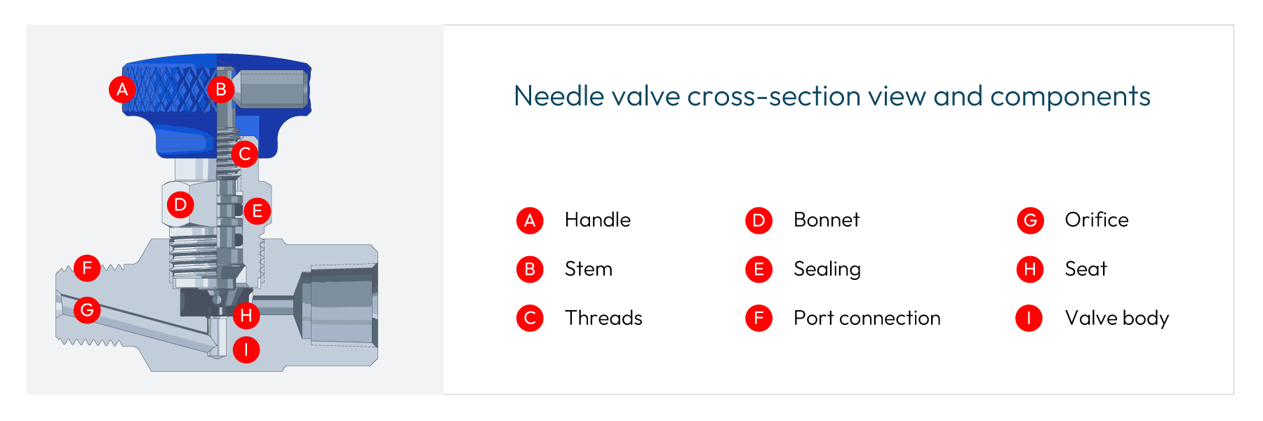
Valve body and ports
The valve body—usually stainless steel, carbon steel, or brass—contains the inlet and outlet ports and the internal flow path. On measurement skids and tube panels, you’ll most often see in-line bodies. Basic measurements are as follows:
- Common connection sizes: 1/8" to 2" (≈3.175–50.8 mm)
- Common thread standards: NPT, BSP, or metric
- Body styles: in-line or angle pattern for tight layouts
Bonnet and stem assembly
The bonnet is the piece assembled into the body containing the moving parts that control flow. Inside the bonnet you’ll find:
- Stem: Fine-pitch threads that turn handle rotation into precise up-and-down travel of the needle
- Packing: Sealing components around the stem (PTFE, FKM, FEPM, graphite, etc.) that keep the media from leaking to atmosphere
- Packing nut: Tightens the packing over time if slight stem leakage develops
Many modern instrumentation needle valves use a non‑rotating stem design. The stem travels through the packing independent of the needle, allowing non-rotational engagement with the seat. That small detail minimizes seat and needle wear, which helps the valve seal longer in high‑cycle or frequently adjusted service.
Orifice and seat
The orifice is the small opening that the media passes through. That’s what gives a needle valve its high pressure drop and precise control at low flow.
The seat is the fixed surface that the needle closes against, surrounding the orifice. Metal seats (like stainless or alloy steel) are common in liquid, high-temperature, or high-pressure service. Soft seats (like PTFE or POM) are often used in gas service when you need a bubble-tight seal and can stay within the seat’s temperature and pressure limits.
Handle or handwheel
The handle is how you operate the valve. It translates your input into stem movement Common handle types are round and T-shaped.
Because of the fine threads on the stem, the user has more control operating from fully closed to fully open. That’s on purpose. The needle valve spreads a small change in orifice size over multiple turns, which makes each adjustment smoother and less jumpy. In practice, that means you can edge closer to the flow you want instead of chasing it back and forth.
How a needle valve works
Once you know the main parts, the way a needle valve works is pretty straightforward. You’re simply moving a needle in and out of a small opening to change how much media can get through. The fine threads and small orifice are what turn that basic idea into a very precise control tool.
Here’s how needle valve positioning works:
- Closed Position: In the fully closed position, the needle tip is fully seated in the orifice. The tapered surface of the needle is pressed into the seat, creating a leak-tight seal. For a properly sized and installed valve with clean media, push it a little past finger‑tight. Over-tightening can damage the seat, especially in brass valves.
- Opening the Valve: Turning the handle counterclockwise lifts the stem through the bonnet threads. The needle retracts straight up away from the seat, opening a narrow gap between the needle tip and seat. Media starts to flow through that small opening.
- Flow Rate Control: As you continue to open the valve, the needle gap increases, allowing less resistance for media flow. The needle can be stopped at any position between fully open and fully closed to fine-tune flow rate.
- Fully Open Position: With the stem fully opened to the backseat position, the needle is entirely clear of the seat. Flow is limited mainly by the orifice and port size.
Needle valve pros and cons
Like any tool in the system, needle valves are great at some things and a less-great fit for others. Knowing where they shine helps you decide when a needle valve is the right call and when you should reach for a different valve style.
Pros
- High-precision flow control, especially at low flow rates
- Leak‑tight shutoff with relatively modest hand torque
- Compact and easy to integrate on panels, manifolds, and skids
- Can be built for high-pressure and extreme temperature applications with the right materials and packing
Cons
- High pressure drop due to the small orifice
- Not suitable for large flows or as the primary process isolation in large pipelines
- Needle and seat at risk of damage by solids and dirty media
- Handle position doesn’t clearly show open/closed like a ball valve handle
How to pick a needle valve
When you’re choosing a needle valve, it helps to walk through a simple checklist. The goal is to make sure the valve matches the media, the conditions, and the application in the field.
- Start with the media that’s flowing through the valve, whether gas or liquid. Identify corrosive properties and whether the media requires any special accommodations.
- Choose the body and bonnet material. 316 stainless steel is the go‑to for most oil and gas, chemical, and high‑pressure work. Brass is fine for moderate conditions with less corrosive fluids, while carbon steel or alloys are reserved for low-cost and non-restrictive environments.
- Confirm pressure and temperature ratings in your environment so you can choose internal valve components that meet those criteria.
- Determine the connections and orifice. Match the thread type and size to your existing tubing or piping. Look at the orifice diameter, not just thread size—it controls flow capacity and pressure drop.
- Pick a seat and stem design. Use a metal seat for high-temperature and high‑pressure services, or a soft seat when you’re working with gas and need a bubble‑tight seal. Pick a non-rotating stem design if the valve will see frequent cycling or adjustments.
| RELATED ARTICLE: Orifice meter installation effects and the need for flow conditioning
Get a needle valve that’s made to measure
Needle valves may be small, but they play a big role in measurement accuracy and flow stability. When you get the material, pressure rating, and seat design right, needle valves deliver reliable control without constant tweaking.
If you’re designing or upgrading a system and you want confidence in your valve choices, Axis Measurement is here to help. We carry a range of needle valves and can work with your team to match instrumentation components to real‑world pressures and temperatures, keeping your system accurate and production on schedule. Contact us to learn more.
Axis is proud to support ASGMT by teaching two measurement classes on September 18 on the following topics:
10:15 am – 12:00 pm Manifold and Direct Mount Systems and Valve Repair hands-on session
11:15 am – 12:00 pm Orifice Meter Installation and the Need for Flow Conditioning lecture class
Visit us at Booth 69!
Axis is proud to support the International School of Hydrocarbon Measurement (ISHM) by teaching three measurement classes on May 13. Topics are as follows:
Effects of Abnormal Conditions on Accuracy of Orifice Measurement
In the field, ideal conditions aren’t just a matter of preference—they are a requirement for accurate measurement. In this class, we will be reviewing the effects of improper installation, physical damage, and poor design on orifice measurement accuracy. Discover how the condition of your orifice installation can affect your measurement accuracy.
Flow Conditioners for Orifice Measurement
Flow conditioners ensure a smooth, even flow with minimal swirl, a fully developed flow profile, shorter upstream length requirements, and accurate measurement in a wide range of flow conditions. In this detailed discussion, we will explore the implementation of flow conditioners to the specific application of orifice gas measurement.
Manifold and Stabilizer Installation
This is a hands-on class demonstrating the installation and repair of manifolds and stabilizers out in the field. Learn how to install a range of measurement devices quickly, efficiently, and correctly for improved performance and to ensure the accuracy of your measurements.
We’re still the same company.
We remain the family-owned business that’s built on quality and dedication to our customers. For over four decades since we opened our doors as RJ Machine, we have made the best-quality products in the business. While we continue to manufacture the products you need at the high caliber you expect, we aren’t just a machine shop. You also trust us to handle more of your measurement needs, and our new name better reflects that.
Our team isn’t changing, either—the owners and employees are the same. You’ll still be working with the same people you always have.
We’re keeping the antler logo.
We first introduced the name Axis as a brand name for our newer products to help them stand out in a crowded market. Axis was named for the axis deer (also called a chital or spotted deer), since many of our customers know their way around a rifle and a deer blind. We chose a name that would resonate with them, and we used a set of crossed antlers as the brand’s logo.
Many of our customers over the years have told us how much they love the logo. So even as we re-evaluated our brand to ensure it would reflect the needs of our changing company, we knew this element wouldn’t change. Much like our commitment to our customers, the antlers aren’t going anywhere.
Our customers still come first.
We’re more than just a supplier or a machine shop. Over the years, we have built a hard-earned reputation for partnering with customers to solve their problems and support their every need. Whether you need a rapid fix or just have a question about a product, our team is quick to respond and get the solution you need. And like always, our after-sales service remains second to none, no matter where you’re located.
We still offer quality products you can depend on.
We continue to design and manufacture the precision-quality oilfield products you need, from manifolds to orifice plates and everything in between, giving you accurate measurement and minimal margin of error. Products are manufactured in Mexico for high volume and maximum value without cutting corners, so we deliver faster than our competitors with better value. We also maintain high inventory levels so you can get the products you need, when you need them, delivered right to your location.
We’re introducing new products, too.
Axis Measurement is a company of innovation. We are constantly expanding and bringing new ideas to the market to improve your measurement. Most recently, we have launched a large-bore, rapid-mount manifold that’s already redefining measurement in the field thanks to its reduced installation time. We hear our customers and the problems they face out in the field, and we are meeting those challenges with innovative improvements.
More patent-pending products are coming soon in competitive product spaces, so stay tuned for more updates.
---
The name Axis has resonated strongly with our customers. Axis is no longer just a brand we make. It’s who we are as a company. And as we move forward into the next 40 years, we’re excited to take that journey together with you.
Want to learn more about Axis Measurement products? Contact us and get the information you need.
Abstract
This paper discusses the effects of poor installations on orifice measurement and the best practices to achieve highest accuracy and performance. Flow disturbances are everywhere in pipelines and industrial applications. Knowing the types of disturbances, their effect on orifice measurement and how to correct those errors is valuable for anyone interested in accurate orifice flow measurement.
What is “Good” Flow
Most flowmeters are affected by the flow that they are trying to measure, orifice plate flowmeters included. Orifice plates measure best in “good” flow conditions and lose accuracy in “bad” conditions. There are several methods to describe and characterize good vs. bad flow conditions. When asked to describe good flow conditions, many users will use the term Laminar. This is a common yet minor misconception in flow engineering.
Laminar vs. Turbulent Flow
Laminar is a flow regime where the flow follows relatively straight lines down a pipe, Figure 1. If you were to follow a particle in the flow, it would go in a straight path and not cross paths with other particles flowing next to it. This is a regime with no turbulence. Laminar flow will happen in low flow and/or high viscous applications. In other words, the momentum forces are low and/or the viscous forces are high. Inherently this makes sense as higher velocities will encourage turbulence and higher viscosities will do the opposite.

As useful tool is the Reynolds number, which is a dimensionless number used to quantify whether a flow application is in laminar flow. The Reynolds number equations is a follows:
Re=VρD/μ
Re = Reynolds number, dimensionless
V = flow velocity, ft/s
ρ = density, lbm/ft3
μ = dynamic viscosity, lbm/s·ft
The numerator of this equation combines the momentum forces in the flow, velocity, density and size. While the denominator are the inertial forces, viscosity. This follows the logic described earlier. The lower the Reynolds number, the more likely the flow regime is in a laminar state. Laminar flow is more likely to exist where the velocity, density or size is small, and/or where the viscosity is high. The commonly accepted value of laminar flow is Re < 4000. As the Reynolds number increases, the flow regime enters a transition phase between 4000 and 10,000. Above 10,000, the flow regime is considered to be turbulent.
Reynolds number - Flow regime
0 – 4,000 - Laminar
4000 – 10,000 - Transition
>10,000 - Turbulent
Turbulent flow, Figure 2, is the opposite of laminar flow in that the flow streams do not follow a straight or regular pattern. In turbulent flow the flow streams cross, small eddies occur, and mixing is more common. The word “turbulent” rightfully has negative connotations. No one wants to be on an airplane and fly through turbulence.

So why is Laminar the incorrect term to describe good flow? It’s not. It’s just not the world in which our flowmeters live. The vast majority of industrial pipelines are in the turbulent flow regime. Virtually all gas flows are turbulent due to the high velocities and low viscosities. Even most liquid flows are turbulent, except for some high viscosity products such as crude oil. Turbulent flow is better for orifice measurement because orifice plates were designed to measure it and their performance is well understood in those conditions.
A side note: Reynolds number is a very helpful in flow measurement. Since it is a dimensionless number, Reynolds can use a single number to describe a flow application. And that number can be used across applications. If the Reynolds number for an application is below 4000, that application is in the laminar flow regime, regardless of the size for example. Reynolds number is used when calibrating a flowmeter. Since the Reynolds number describes the flow in a single number, users can calibrate on one fluid and use the flowmeter in another fluid, knowing the performance will match at equal Reynolds numbers.
Flow profile
A better way to describe understand good vs. bad flow is the presence or absence of flow disturbances. Long, straight, unobstructed pipe will create undisturbed flow. The addition of common pipe elements will create disturbances. Common pipe elements can include single elbows, tees, two elbows in series, partially closed valves, pipe reductions or expansions, thermowells, and many more.
Just like the Reynolds number is a tool to understand the flow regime, the flow profile is a tool to visualize whether flow is disturbed or not. The flow profile attempts to show the velocity at difference points across the diameter of a flowing pipe. This can be physically measured in several ways such as with a single point Pitot tube sensor or with more complex tools such as laser doppler velocimetry. Typically, the view is across a full diameter, crossing through the midpoint of the pipe. A typical flow profile looks like Figure 3 for turbulent flow. Each arrow represents the velocity at points across a diameter of the pipe. The velocities are higher in the center of the pipe and lower near the pipe walls.

The friction on the pipe walls causes drag which slows down the fluid flow nearest to it. As the flow continues down the pipe, the next layer away from the pipe wall is slowed down slightly less. And so on until the effect of the pipe wall friction no longer affects the velocity. This is called the boundary layer effect and is created whenever flow passes over a surface. Notice the shape of the Figure 3 profile in turbulent flow is different than the shape in Figure 1. Laminar flow has a characteristic “bullet” shaped profile and turbulent has a flatter shape.
Well-developed flow is created when the boundary layer is fully established without disturbances. Put another way, well developed flow will not change its profile as it moves down the pipe. In the industrial flow measurement world, it’s also the definition of good flow and is very important in understanding flow through an orifice.
Power law estimation
When comparing whether a flow profile is well developed or not, a useful tool is the power law estimation. The power law gives a numerical estimation of a well-developed profile. The power law equation is:
u/umax = (1-r/R)1/n
u = velocity at measurement point
umax = max velocity in pipe
r = radius at measurement point
R = pipe radius
n = power
A value of n = 7 is typically used to fit the velocity profile for fully developed, turbulent flows. A higher value of n creates a flatter profile. A lower value creates a more bullet shape profile associated with laminar flow. A power law curve where n = 7 is shown in Figure 4.

As flow is disturbed with the addition of pipe elements, the flow profile will change. For example, flow through a single elbow creates a skewed profile. The high velocity “core” of the pipe will be pushed to the opposite wall of the pipe, creating an asymmetry where the maximum velocity is no longer in the middle of the pipe. Single elbows and other elements can create asymmetry in the flow profile which is shown well in Figure 5.

Swirling flow
The flow profile does not capture another type of flow disturbance called swirling flow. Swirling flow is when the flow has a crossflow element. Without swirl the flow will run straight down the pipe, with 0° in relation to the centerline of the pipe. If crossflow is present, the flow streams can have a swirl angle, up to 20° in severe cases.
There are two general types of swirl disturbances, Type 1 and Type 2 swirls. Type 1 swirl moves in one directional rotation across the pipe. This is also known as whole body swirl, Figure 6. Close coupled double elbows out of plane are a common cause of Type 1 swirl, along with headers, pumps and compressors. Type 2 swirl introduces two counter rotating swirls rotating in opposite directions, Figure 7. This is usually created after single elbows.


Orifice plate flow measurements
Orifice plates measurement have a century-long track record of continuous use and improvement in industrial applications. No other flow technology has the international volume of understanding and acceptance as orifice plates. Orifice plates are often described as “a hole in a plate” and often ridiculed for that simplicity. Yet it is the simplicity of an orifice plate that makes it so elegant. Leonardo da Vinci once said, “Simplicity is the ultimate sophistication”. The design of the orifice plate makes it possible to manufacture with precision and repeatability. Making one orifice plate measure the same as the next one with matching dimensions. A dimensional inspection is all that is needed to “calibrate” an orifice plate.
Knowing that two identical orifice plates will measure the same (within known uncertainties) is one of the reasons why they are the most widely used industrial flow technology even after 100 years. In today’s world, a user can replace an orifice plate and know the uncertainty of the measurement will not change, even without a flow calibration – something no other flow technology can match!
This also means that a flow calibration once done on a known orifice plate size, can be applied to all other matching orifice plates. Over the decades a massive database of traceable orifice calibrations was completed and used to create the de facto standards for orifice flow measurement. The American standards are the AGA Report No 3 and API 14.3 standards for natural measurement using an orifice plate. The international standard for orifice plates is ISO 5167.
The orifice performance in that technical database (which includes over 30,000 data points!) was tested in well-developed flow conditions. The standards confirm that measurement in matching conditions and dimensions will perform at custody transfer levels of accuracy. And since all the data points were tested in well-developed flow conditions, the standards require the same for accurate measurement.
Effect of flow disturbances on orifice measurement
If a user’s flow conditions are not well developed, with asymmetric or swirling flow, the accuracy will be affected. The effect on accuracy will depend on several factors, including the type of disturbance and the relative distance of the disturbance to the orifice location.
As the distance from the disturbance to the orifice plate increases, the flow will naturally return to a well-developed state due to the turbulence in the flow (turbulence helps us here). The distance needed to return to well-developed flow depends mostly on the type of disturbance. The AGA/API standards recommend up to 44 pipe diameters of straight pipe after double elbow to achieve well developed flow.
Shown below are two sets of flow calibration data from Mattingly and Yeh measuring three different orifice bore sizes (beta ratios) at various distances from a disturbance. Figure 8 shows single elbow effects.Figure 9 shows effects from close coupled, double elbows out of plane.


The effect of the disturbance diminishes with distance, approaching zero effect. Notice the effects on accuracy of the orifice plate measurement can be up to 5% after a single elbow using a high beta ratio. The effect lessens using smaller beta ratios. Also notice the x-axis scale of the double elbows chart is much larger than the single elbow chart. This confirms that Type 1 swirl has a much longer lasting impact on flow measurement than Type 2 swirl.
Improving flow conditions
A user can make a determination about their installation knowing the above information. They have three options available to them:
- The user could plan the measurement point as far as possible from the disturbance. The more distance means the more likely the flow is well developed at that point. Some users may have plenty of straight pipe in their system and can meet the minimum requirements in the standards. For most users, creating the necessary straight inlet piping will come with additional expense.
- The user can accept the additional uncertainty that comes with a bad installation. This might be a fine solution in applications with low accuracy requirements. But most industrial applications cannot accept accuracy shifts on the order of ±5%.
- The user could follow the most common practice in the industry: use a flow conditioner.
Flow conditioners
The user of flow conditioners is an industry best practice for ensuring optimal flow measurement with an orifice plate. Flow conditioners come in a variety of designs but have one common goal: to condition the flow to well-developed conditions ahead of an orifice flow measurement point regardless of the disturbance ahead of it.
In the AGA Report No. 3, Section 2.3.1.7 “Flow Conditioners” classifies flow conditioners into two categories: straighteners and isolating flow conditioners.
“Flow straighteners are devices that effectively remove or reduce the swirl component of a flowing stream but may have limited ability to produce the flow conditions necessary to accurately replicate the orifice plate coefficient of discharge database values. Isolating flow conditioners are devices that effectively remove the swirl component from the flowing stream while redistributing the stream to produce the flow conditions that accurately replicate the orifice plate coefficient of discharge database values.”
Flow straighteners
Flow straighteners are low blockage, swirling reducing flow conditioners. Common examples of flow straighteners are tube bundles, example shown in Figure 10 and fin-type straightening vanes, example shown in Figure 11. Tube bundles can be designed with 19 or 7 tubes concentrically grouped in the pipe. The terminology around these can be confusing as tube bundles are sometimes sold as straightening vanes, but both fall into the category of flow straightener as described in AGA 3.
These types of flow conditioners are designed to remove swirl with their elongated dimensions. But since they are low blockages, they do very little to correct he asymmetry in the flow profile. In fact, Mattingly and Yeh also showed that flow straighteners can actually make asymmetry a more persistent flow disturbance, lasting much longer in terms of distance. This is because the flow straighteners will capture the asymmetry entering each tube and reduce the type 2 swirl. By reducing the type 2 swirl, the natural turbulence is diminished and the asymmetry does not break down as quickly.
In short, flow straighteners are not recommended for orifice plate measurement.


Isolating flow conditioners
Isolating flow conditioners have a blockage factor that forces the flow profile to redistribute as it passes through. This redistribution controls both the asymmetry and swirl disturbances. The design is typically a perforated plate with multiple holes designed to create a well-developed flow profile as soon as possible after the plate.
The search for the ideal pattern of holes to do this job was the subject of much research in the 1990’s as the need for flow conditioning became more and more relevant. A summary of the research from researchers such as Laws, Karnik, Zanker, Gallagher and others is fascinating but outside the scope of this paper. The most widely accepted design of this research was developed by Laws and has become known as the NOVA 50E design.
The NOVA 50E design, Figure 12, is a multi-hole flow conditioner with concentric rings of openings. 16 smaller holes around 8 midsized holes around one large central opening. The size and position of each hole is meant to stimulate the formation of a well-developed flow profile regardless of upstream disturbances. The “50” designation indicates that the plate has approximately a 50% blockage area in the flow path. The success of this design is the balance of three factors: 1) enough blockage to redistribute the flow profile, 2) large enough holes to allow passage of particles and 3) enough opening to reduce the pressure loss across the plate as much as possible. The NOVA design meets the requirements of AGA 3 Section 2.5.5 and APPENDIX 2-D.

The design is universal for all flow conditions and disturbances. This advantage means a user can have one design flow conditioner for various pipeline installations and conditions. And it gives the user the assurance that most flow disturbances will be removed prior to flow measurement. For as much testing and research has been done of the effects of flow disturbances in a pipe, a user does not know the flow regime and development of their flow profile. Having a flow conditioner improves orifice plate measurement in all standard applications.
Conclusion
The use of a flow conditioner is recommended for all high accuracy orifice plate measurements. The recommended type of flow conditioner is the NOVA 50E design to remove most flow disturbances such as asymmetry and swirl. And users will benefit from the assurance that a well-designed flow conditioner will remove any unknown flow disturbances and problems that could diminish their measurement accuracy.
[1] Effects of pipe elbows and tube bundles onselected types of flowmeters, G.E. Mattingly, T.T. Yeh, Flow Measurement Instrumentation, Vol 2, January 1991
[2] US Patent 5,341,848 “Flow Conditioner”, 1994
We want to hear from you.
