

That is why the question of standard bore vs. dr plate matters, and why it matters most at custody transfer. We will explore the differences between these two types of orifice plates and the applications where they are best suited.
What is a standard bore orifice plate?
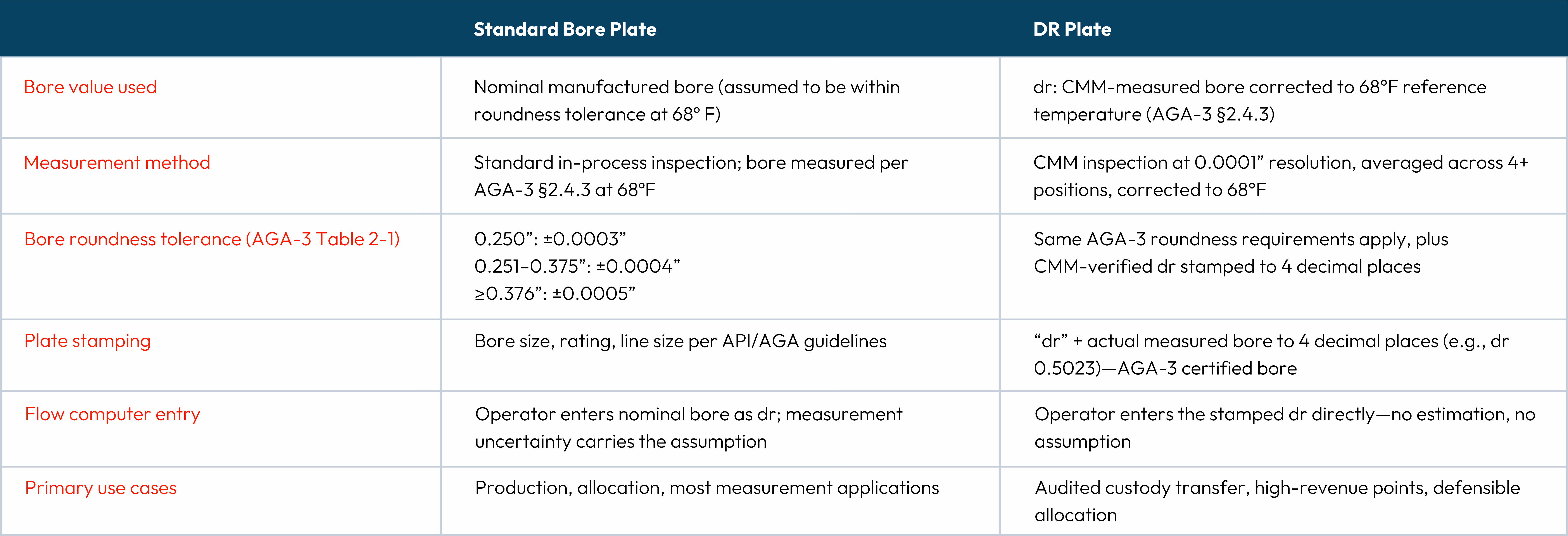
A standard bore plate is a differential pressure primary element—a precisely machined disc installed between flanges or metering devices to create a measurable pressure drop across a flowing stream. Flow rate is calculated from that differential using the AGA-3/API 14.3 discharge coefficient equation, which is a function of the beta ratio: the bore diameter divided by the pipe inside diameter.
Standard bore plates are manufactured to AGA-3/API 14.3 dimensional requirements. Bore roundness, flatness, edge sharpness, bevel angle, and upstream face finish are all held within specification. AGA-3 Section 2.4.3 requires that the bore diameter (dm) be measured as the arithmetic average of four or more evenly spaced diameter measurements at the inlet edge.
AGA-3 Table 2-1 defines the allowable roundness tolerance by bore size. The maximum any individual measurement may deviate from the mean is as follows:
- ±0.0003” for bores ≤0.250”
- ±0.0004” for bores 0.251”–0.375”
- ±0.0005” for bores 0.376”–1.000”
At Axis Measurement, our standard bore plates are manufactured to Axis internal process controls that meet or exceed AGA-3 roundness requirements. For the vast majority of oil and gas measurement applications, standard bore plates deliver reliable, repeatable, and fully compliant performance.
RELATED ARTICLE: Why use forged-material components?
What is a dr orifice plate?
The “dr” designation comes directly from AGA-3/API 14.3 notation. In the standard, two reference-temperature values define the beta ratio used in the flow equation:
- dr (lowercase d) = the reference orifice plate bore diameter. This is the bore calculated at reference temperature (68°F) per AGA-3 Equation 2.1. AGA-3 Section 2.3.1.2 explicitly defines dr as “the certified or stamped orifice plate bore diameter.” This is what is stamped on a dr plate.
- Dr (uppercase D) = the reference meter tube internal diameter at 68°F. It is defined in AGA-3 Section 2.3.1.5 as the “certified meter tube internal diameter.” This is a pipe property entered into the flow computer for custody transfer calculations. It is not stamped on the orifice plate.
Together, dr and Dr define the reference beta ratio (βr = dr/Dr), which is what the AGA-3 flow equation requires. The key question for measurement accuracy is: how precisely do you know dr?
A dr plate is one where the bore has been individually measured via CMM (Coordinate Measuring Machine) at 0.0001” resolution across four or more evenly spaced positions. That verified dr value is then stamped directly on the plate, with“dr” followed by the actual bore to four decimal places (e.g., dr 0.5023). There is no nominal. What is stamped is what was measured and corrected.
As a result, the value on your plate is the AGA-3 certified dr and is ready to enter directly into the flow computer. It is not an estimate or a nominal bore within a tolerance band, but a CMM-measured, temperature-corrected, stamped value.
Why bore precision compounds in your flow calculation
Flow rate in an orifice meter is proportional to β² = (dr/Dr)². A 0.001” error in a 0.500” bore is a 0.2% bore error but a ~0.4% flow error. At a custody transfer point flowing 5,000 MMBtu/day, a 0.4% flow error is 20 MMBtu/day you can't account for. Multiply that by the number of meter runs in your system and the number of days in a measurement dispute, and the conversation about a dr plate pays for itself pretty quickly.
Standard bore plates operate within the tolerance band that API/AGA compliance defines. That band is designed to be sufficient for most applications. DR plates replace the tolerance band with a verified, stamped dr. The bore’s contribution to total measurement uncertainty is no longer assumed—it is documented.
When to use a standard bore plate
Standard bore plates are the right specification for the majority of oil and gas measurement applications where API/AGA compliance defines the accuracy floor:
- Production allocation and well-level measurement
- Non-custody or lower-stakes measurement points
- Applications where standard tolerance uncertainty is within acceptable limits
- Cost-effective meter run builds without sacrificing compliance
- Standard orifice fitting installations in production or gathering systems
For most operations, standard bore plates deliver consistent, repeatable performance that meets every regulatory and contractual requirement.
When to use a dr plate
dr plates are specified when measurement certainty needs to be verified, documented, and defensible:
- Custody transfer points with significant revenue throughput
- Audited measurement points requiring traceable bore documentation
- Allocation disputes or reconciliation systems where measurement must be defensible
- Gas balancing or system studies requiring a known, verified beta ratio
- Any point where you need to know dr—not estimate it—when entering the flow computer
- Contract or customer specifications requiring individual bore measurement certificates
Dr plates are also the right call when a measurement point will face audit review, or when a discrepancy will need to be traced back to a documented bore value.
Which plate does your application need?
Both plate types are built to API 14.3 / AGA-3 standards and perform reliably in the field. The core difference is straightforward:
- Standard bore: compliant, cost-effective, operationally measured at 68°F, and right for most applications.
- dr plate: dr measured at 68°F, stamped to four decimal places, and CMM-documented—the exact value for your flow computer and your audit file.
If you are evaluating which orifice plate your application requires, the decision comes down to how much of your measurement uncertainty you need to know vs. how much you are comfortable assuming. Our team can help you work through that before you install. Reach out to us at sales@axismeasurement.com or give us a call at 830-693-7493 for more information.
Technical references:
AGA Report No. 3 / API MPMS Chapter 14.3 Part 2: “Orifice Metering of Natural Gas and Other Related Hydrocarbon Fluids: Specification and Installation Requirements,” 4th Edition (AGA/API, 2000/2003). Section 2.3.1.2, 2.3.1.5, 2.4.3, and Table 2-1.
Abstract
This paper discusses the best practices of manifold, stabilizer, and tubing installations and their effects on natural gas measurement and safe operations of personnel when using with an orifice meter. During natural gas measurement, pulsation that occurs at the orifice meter creates detrimental effects to reliable measurement leading to unaccounted-for (UAF) gas. With gas volumes at the highest levels in the market today and the value associated with these volumes, gas metering demands the highest possible accuracy. Additionally, safe operations should be of the highest priority to ensure minimal risk and prevent harm to any personnel.
What Affects “Accurate” Measurement
Field research has shown that Square Root Error (SRE) and Gauge Line Error (GLE) lead to high levels of UAF gas. Both types of error can be directly associated with pulsation caused by piping configurations, compressors used in stations, valves and regulators. Manifold, Stabilizer and tubing installation cannot impact SRE but through best practices they can reduce GLE.
Best Practices for Tubing Installations
Impulse lines in tubing installations are small-bore tubes which are used to connect the up and down stream points of pressure to an instrument for flow measurement. When measuring flow, a primary element such as an orifice plate, nozzle or other flow tool is used to create differential pressure which is the measured with an Electronic Flow Measurement (EFM) flow computer.
Impulse lines are known to lead to incorrect measurement if improperly designed or installed. These problems can be exacerbated by many aspects:
- Suppression of pressure signal
- Internal blockage
- External leakage at connections
- Condensate buildup
- Different temperatures
Design and Configuration
All tubing and accessories should be confirmed as rated for the associated process for temperature and pressure. The system cannot be implemented if there is any piece of equipment, including couplings, which is not fully rated.
The EFM should always be located above the orifice meter to facilitate drainage of any liquids that may form internally. Additionally, impulse lines throughout the system between the orifice meter and EFM must slope upwards and avoid any teeing off to or from existing lines. In cold weather, it is always beneficial to heat trace or enclose to prevent the internal condensate buildup from freezing. Condensate will retain internally along the walls regardless of the slope, so it is best practice to assume condensate exists.
Reduction in the overall length of the tubing can improve the impact of most of the problems listed. If you are experiencing pulsation, the overall distance must be less than 24”. If no pulsation is existing, the overall length is not important but should be minimized where possible. The ability to shorten the length of the tubing can be limited by the need to isolate the EFM from high process temperatures, the location of the EFM - for example if an enclosure is far away from the orifice meter, or the need to incorporate valves or systems to make it possible to remove the EFM, vent internal pressure, or bridge an equalizing path between the high and low side without shutting down the system.
It is essential when implementing tubing set ups to ensure equidistant lines between the up and down stream tubing to the EFM. Bending will increase the length of the tubing and this lengthening should be considered. Ensuring equidistant tubing will lead to equal head pressure avoiding false differential pressure, reduce temperature differences, and synchronize response time and readings for both up and down stream readings.
Comparably, the internal diameters of the tubing and internal bores of integrated parts should be equal throughout the system. For example, if you are using a 3/8” bore valve or manifold, the tubing should be at minimum a 3/8” internal diameter. Note that 3/8” tubing will indicate the outer diameter and not the internal diameter. It is recommended that all tubing should be with a minimum internal diameter of 3/8” or greater.
For longer length systems, it is important to ensure that the piping is well maintained and supported to prevent vibrations or sagging in the lines. Vibration in extended lengths can lead to damage of couplings leading to external leakage. The natural frequency of any unsupported lengths should not overlap with any frequencies of the system.
Best Practices for Manifold and Stabilizer Systems
Stabilized connectors, or close coupled systems, were designed out of the need for a more robust system due to field failure of typical nipple-ball valve to EFM set ups. Failure in previous set-ups was caused by horizontal force applied to the EFM. This horizontal force in combination with extended orifice tap to EFM distances creates a moment of force beyond the strength of the nipple-ball valve connection leading to catastrophic failure and release of media to the atmosphere endangering the system including all surrounding personnel.
To address the failures, the stabilized connectors were designed to provide a means to transfer the radial load away from the NPT threads. This forms a stronger connection between the pipe thread and the orifice fitting while eliminating the tendency for leakage to occur at this juncture. Each stabilized connector is supplied with a “shoe” that is utilized to create a larger, flat footprint at the surface of the orifice meter. It is important that the shoes be aligned as shown in Figure 1 to provide the full benefit of the extended surface area. Misaligned shoes can create pressure points leading to improper distribution of forces. The compression nut must also be tightened to the recommend torque rating to ensure full transfer of forces from threads to the stabilized connector.

During installation, the level height for the stabilizer flanges shown in Figure 1. and the orientation of the stabilizer flanges shown in Figure 2. are essential to creating a good seal. When adjusting your system to level the flange heights, it is important to always adjust the higher flange down to the level of the lower flange. Raising a flange once installed can damage the seal at the threads leading to leakage unless the threads are re-taped.

When working in a system that connects pressure to an EFM that has been calibrated, all pressure must be brought on gradually to avoid any static line shift in the EFM’s readings. Rising stem needle valves accomplish this via multi-turns to open while a ball valve can only be operated from open to close. Instant pressure to the diaphragm seal of an EFM via this method will cause a static line shift.
When selecting a manifold to pair with stabilizers in close coupled systems, the internal bore should be large orifice sized at 3/8” and maintain a maximum distance from orifice taps to the EFM of 18”. On horizontal to vertical installations, it is necessary to ensure proper space to operate the fitting as there can be a clash during operation. Typical horizontal to vertical installations will utilize a 90-degree manifold. Due to the orientation of these installations, it is necessary to ensure that the manifold has both rod out and drain ports for cleaning condensate and waste that can build up internally. In general, internal bores of manifolds should be designed to be self-draining towards the process or vent.
Detecting and Preventing Leaks
During startup and maintenance of systems there is a need to detect and prevent leaks as there is a cost financially and for the general welfare and safety of personnel. Leaks in systems are common therefore it is important to understand how to prevent leaks, how to test and find leaks, and how to address leaks. In general, tubing systems are more susceptible to leakage than close coupled stabilizers to manifold system.
Leak prevention should be our number one priority. Proper tape methods and torque specifications should be adhered to on all threaded connections. When following torque specifications, it is important to properly tighten and not overtighten using proper tools such as torque wrenches or gap inspection gauges. Accessibility during the design stage of a system is important for critical or often accessed components during replacement and maintenance. Proper placement of tubing to avoid high traffic areas and ensure proper support to avoid vibrations must be achieved. When valves are in operation, they should be fully open or closed, and throttling should be avoided when possible.
Typical leak detection methods such as liquid leak detection or snooping are always necessary for external leakages. All connections should be inspected including preassembled connections such as bonnets and upper stems of valves. It is possible that internal parts such as valve seats can leak. Pressure decay methods where any possible leak can be associated with a decrease in internal pressure should be considered as well. For 5 valve manifolds, a method or process should be used such that all 5 valves are confirmed to be bubble tight. Due to the small molecule size, helium is a good choice for testing medium.
Customer Challenge
A customer was considering switching from a competitor’s manifolds to Axis manifolds. They wanted to be certain that our products were right for their steam measurement application, which saw temperatures of 200–250°F and was isolated from the transmitter via glycol-filled drip pots. An incorrect seat or seal material could lead to:
- Soft seat deformation under temperature or pressure, leading to loss of bubble-tight shutoff
- Chemical incompatibility causing stem seal failure and fugitive emissions, which are hazardous to personnel
- Premature manifold replacement and unnecessary, unplanned downtime
Technical Considerations
Axis Measurement manufactures 3/8” bore 5‑valve manifolds used in natural gas, petrochemical, and steam measurement applications. These manifolds rely on soft seats to ensure bubble‑tight shutoff and stem seals to eliminate fugitive emissions. Proper selection of both is essential to maintain safe operation under extreme conditions and corrosive environments.
Axis technical guides define how materials should be selected based on process pressure, temperature, and chemical compatibility. This includes ETFE (Z), POM (D), and PEEK (P) for seats, and FKM (V) and FEPM (A) for seals. Pressure ratings are driven by the soft seat, while chemical compatibility is based primarily on the stem seal selection. The temperature rating is determined by the temperature limits of the seat and stem seal selections.
- ETFE (Z) Soft Seat: The maximum operating pressure limit for ETFE is 2,000 psi. It’s suitable for Class 150, 300, and 600 service, has the lowest coefficient of friction, and is excellent for low-temperature natural gas service up to 200°F. However, it’s not ideal for steam applications above that temperature.
- POM (D) Soft Seat: With a pressure capacity of up to 6,000 psi, this seat supports Class 900 and 1500 service. It has excellent rigidity and superior resistance to cold flow, allowing for a higher pressure rating. At pressures below 2,000 psi, it’s susceptible to leakage due to this rigidity. With a limit of 200°F, it’s not ideal for high-temperature steam applications.
- PEEK (P) Soft Seat: This seat has a temperature range of 200–400°F, making it suitable for sustained high-temperature applications. It’s rated for pressures up to 6,000 psi, and it’s recommended when safety margins are required for possible upsets.
- FKM (V) Stem Seal: This seal has excellent resistance to hydrocarbons, oils, greases, and fuels, and it performs in temperatures as low as -15°F. As a result, it’s acceptable for glycol service.
- FEPM (A) Stem Seal: A better choice for certain petrochemical applications, this seal has superior resistance to amines and high-H₂S environments. It’s rated for temperatures as low as -4°F.
Technical Recommendation
We developed failure examples for each combination of seat and seal. If we recommended a POM seat, it would reach its thermal upper limit in the course of regular operations. The risk of thermal softening would lead to seat deformation. Further temperature spikes in a steam upset could cause shutoff loss, steam leakage, transmitter damage, and manifold pressure test failure, leading to a shutdown or safety incident.
This is why we specified a PEEK soft seat for the customer. It matched their steam scenario of 200–250°F, ensuring safe operation under both normal and upset conditions. FKM is a suitable seal option for steam/glycol systems, so we recommended it as the sealing material.
Project Outcome
By selecting PEEK seats and FKM stem seals, AXIS delivered a solution that:
- Withstood the customer’s operating temperature range
- Provided a safety margin for unexpected process upsets
- Complied with process pressure conditions
- Maintained bubble-tight integrity
- Reduced risk of fugitive emissions
- Ensured long-term reliability of the manifold and transmitter installation
The customer adopted the AX6M5SPFLSSVP manifold with confidence that its material configuration matched the demands of their steam measurement system.
Key Takeaways
- Always match seat and seal material to both pressure class and temperature, not one or the other.
- Seat selection dictates pressure rating, while stem seal selection dictates chemical compatibility.
- Steam applications often require PEEK, especially above 200°F.
- Incorrect material selection leads to seal failure, safety hazards, and downtime.
- Engineering support is critical to ensuring safe final configuration.
The third and newest shop—housing turnkey manifold and instrumentation production—recently expanded its capabilities by adding Swiss‑type CNC machines.
This transition will manage increasing demand and support high‑volume production needs. It also aligns with broader operational actions, such as LEAN implementation, capacity modeling, and a strategic shift from push to pull production. More than just an equipment purchase, this is a structural evolution in the way Axis manufactures precision components like orifice plates and manifolds at scale.
Business drivers for adding Swiss machines
As we began seeing more customer demand across the manifold and instrumentation product lines, leadership recognized that traditional CNC turning centers and lathes were being pushed beyond their optimal range for small‑diameter, high‑volume components.
To remain competitive in lead time, pricing, and quality, Axis needed a more efficient production method. Swiss‑type CNC machining provided that solution.
1. Increased demand for small, precision components
Axis produces a range of small, tight‑tolerance components ideally suited for Swiss machining, such as retainers, glands, valve components, and other small‑diameter features critical to natural‑gas measurement assemblies. These parts often require:
- Tight concentricity tolerances
- Consistent surface finishes
- High repeatability across thousands of units
- Stainless‑steel machining expertise
Swiss machines are the ideal platform for producing thousands of units with minimal operator intervention. Unlike traditional turning centers, Swiss machines support the workpiece close to the cutting tool, dramatically improving stability for long, slender parts. The result is greater dimensional accuracy and reduced variability, which are essential for measurement‑critical assemblies.
| CASE STUDY: Seat & seal selection in steam measurement manifold
2. Capacity constraints in the existing machining footprint
The manifold and instrumentation shop is one of the most versatile areas in the Axis footprint. It supports chemical zinc plating, raw material storage, overflow storage, CNC milling, lathe work, hydrotesting, QC, packaging, and shipping—all under one roof.
This product and process mix began to affect workflow, WIP accumulation, and scheduling predictability. Introducing Swiss machines helped relieve bottlenecks previously absorbed by traditional lathes. High‑volume, small‑diameter components can now be isolated to a process built specifically for that purpose, freeing conventional CNC capacity for larger and more complex parts.
3. Strategic push toward LEAN and flow efficiency
Axis has intentionally moved toward LEAN manufacturing principles. While certain production areas were originally designed with work‑cell logic in mind, intuitive layout does not automatically equal optimal flow. However, Swiss machining aligns naturally with LEAN objectives due to its:
- Single‑setup multi‑operation cycles
- Reduced part handling
- Lower queue accumulation
- Predictable cycle times
By consolidating multiple turning and secondary operations into continuous, automated runs, Swiss machines reduce WIP and compress lead times. This directly supports pull‑based production.
4. Lead time reduction as a competitive advantage
Axis differentiates itself through responsiveness, with operational commitments to next‑day shipping and rapid order fulfillment. Swiss machining strengthens this advantage by minimizing setups, enabling unattended or lights-out runs, reducing manual intervention, and improving schedule reliability.
For customers in upstream and midstream natural gas operations, downtime is expensive. When measurement components are needed, they need them fast—and they need them right the first time.
Implementation approach
Adding Swiss machines required more than simple equipment installation. The integration had to align with space constraints, existing workflows, LEAN initiatives, and long‑term capacity planning. Our approach was deliberate and included these steps:
1. Space integration
The new Swiss machines were placed within the manifold and instrumentation area, which already accommodates diverse machining operations. Because the shop supports both medium‑mix and high‑volume product types, planners mapped machine placement around these priorities:
- Proximity to raw bar stock storage for fast replenishment
- Isolation from plating processes to prevent contamination
- Accessibility for QC and assembly teams
- Alignment with future LEAN cell design
2. Production trials
Early high-volume production runs (such as 3,000 stainless‑steel glands and retainers) served as pilot programs to validate performance assumptions. These trials evaluated:
- Cycle time performance
- Tool wear patterns in stainless applications
- Setup repeatability
- Material handling flow
- Capacity impact relative to existing machines
The data collected provided baseline costing and throughput metrics, improving quoting accuracy for high‑volume programs and building customer confidence in delivery commitments.
| RELATED ARTICLE: Why use forged-material components?
3. LEAN roadmap integration
Swiss machining was integrated into the broader LEAN Implementation & Operations Improvement Plan led by Kaufman Global. Our activities included:
- Mapping Swiss‑compatible SKUs
- Redesigning product families for flow
- Planning material movement paths
- Establishing standard work
- Identifying cycle‑time and scrap‑reduction opportunities
A Rapid Performance Evaluation (RPE) reinforced a critical insight: new capacity must support full-system transformation. Alignment with value streams and flow principles will reduce complexity. At Axis, Swiss machining is a way to drive operational improvement, not just incremental output.
Operational impact
The addition of Swiss‑type CNC technology has already produced measurable improvements across our operations.
- Cycle time reduction: Swiss technology reduces multi‑operation workflows into single‑setup continuous runs, lowering cycle times and reducing WIP in the machining queue.
- Expanded volume: Axis previously relied on lathes and CNC mills, which are less efficient for long‑run, small‑diameter precision parts. Swiss machining enables stable production of thousands of units with reduced operator intervention.
- Improved footprint: Swiss machines free up traditional CNC capacity for larger or more complex parts. However, integrating them highlighted the need for value stream realignment, showing that an intuitive layout does not always equal true flow efficiency.
- Inventory control: The predictable cycle times and consumable patterns of Swiss machining support Axis’s broader goals around improving costing systems and inventory tracking.
- Customer value: Swiss machines support Axis’ commitment to precision manufacturing, rapid delivery, and engineering excellence.
Get operational excellence with every part
The introduction of high‑volume Swiss machines marks a pivotal evolution in our manufacturing footprint. This equipment enhances machining efficiency, supports LEAN transformation, improves lead times, and strengthens our competitive positioning. With Swiss machining in place, we are better equipped to deliver on Axis’ strategic goals for 2026 and beyond.
Need high‑volume, tight‑tolerance parts essential to natural‑gas measurement systems? Contact us and get components that are made to measure.
These flaws weaken the part and affect long-term system performance. Defects can cause inconsistent or distorted flow profiles, reduced pressure‑handling capability, increased risk of cracking or field failure, and costly rework, scrap, and downtime.
Material selection and quality directly affect accuracy and uptime. At Axis Measurement, we’re removing some doubt in critical items by utilizing forgings into our process. Keep reading to find out how.
Eliminating porosity during forging
We address the porosity issue at the source by using true near-net-shape forgings to manufacture our manifold bodies and large flow conditioners. Unlike standard bar stock, the forging process creates a denser material with a directional and continuous grain flow that follows the shape of the part. This gives you higher post-machining mechanical strength and improved fatigue resistance, even in the most demanding applications.
We also use fully killed steel for some of our large-diameter products (size 16”–36”). By completely deoxidizing the steel during solidification, we can prevent gas pockets from forming. The superior raw material ensures uniform density in oversized sections with zero internal voids. The result is the highest-quality base material possible for forging.
Product advantages of forged materials
Switching to forged materials gives you an immediate mechanical edge with your measurement products:
- Manifold Bodies: Forged bodies deliver unmatched structural integrity and bubble-tight sealing for leak-proof performance. The dense material dramatically improves fatigue strength and corrosion resistance, extending your valve life.
- Flow Conditioners: Precision-machined from dense forged stock, these products deliver repeatable, fully developed flow profiles at diameters ranging from 2” to 36”. They provide superior performance in high-pressure, unrefined gas service where continuous flow could expose flaws in lower-quality materials.
| RELATED ARTICLE: Axis implements high-volume Swiss machines
End-user benefits from forged materials
Choosing forged materials is a strategic decision that affects the long-term health of your infrastructure—and your bottom line. By moving away from cast or non-forged stock, you can expect several key outcomes that improve both field performance and financial predictability:
- No Porosity: By using true near-net-shape forgings and fully killed steel, we address the root cause of material failure. This process ensures a dense, superior structure, minimizing internal voids and hidden defects that can be exposed when the component is in service.
- Greater Reliability & Safety: Forged components are engineered to withstand intense pressure cycling and the harshest field conditions. The directional grain flow that emerges from the forging process provides structural integrity under pressure.
- Improved Accuracy: Precision starts with the base material. A dense, uniform material structure ensures predictable flow and measurement stability. This is critical for maintaining fully developed and repeatable flow profiles for accurate custody transfer.
- Lower Ownership Costs: While the initial investment in quality materials is key, the real value shows up over the life of the asset. Forged parts need less rework, have fewer mechanical failures, and have a significantly longer service life. This reduces lifetime maintenance costs and prevents expensive downtime.
| CASE STUDY: Seat & seal selection in steam measurement manifold
Why customers choose our forged solutions
Forged materials offer superior strength and longevity, but that’s not your only consideration when sourcing measurement components. You also need traceability and ongoing support from your supplier. This is where Axis stands out.
- Proven performance in gas measurement and critical service
- Robust supplier verification and certification standards
- Commitment to material traceability and quality
- Engineering partnership that solves real‑world field problems
Upgrade to forged reliability
Made with forged materials, our manifolds, stabilizers, and flow conditioners eliminate porosity for better in-field performance and safety. Contact us and get components that are made to measure.
Thermowells are used to protect temperature sensors in demanding applications like oil and gas. They also let field techs replace a failed sensor without shutting in the line.
In this article, we’ll explain what a thermowell is and how it works.
What does a thermowell do?
A thermowell is a cylindrical fitting that’s closed at one end and open at the other. It mounts through the wall of a vessel or process piping. The temperature sensor (a thermocouple, RTD, or thermometer) slides into the open end from outside the process. The process fluid never directly contacts the sensor, only the thermowell.
This means the thermowell shields damage from the process fluid so the temperature sensor remains accurate. As a result, there is no risk of damaging probes due to high pressure, high velocity, corrosive chemistry, or erosion. Failed sensors can also be easily removed or replaced without isolating the vessel or line.
How does a thermowell work?
A thermowell works by creating a controlled heat-transfer path between the process fluid and the temperature sensor. When you immerse a thermowell in a flowing process, heat moves in this sequence:
- Process fluid (the medium being measured—oil, gas, water, etc.)
- Thermowell wall (the metal tube itself)
- Sensor tip (where the thermocouple junction, RTD element, or thermometer bulb sits)
- Sensor output (the electrical signal or reading you see)
Each step in that chain introduces a delay in heat transfer. The more metal between the fluid and the sensing element, the longer it takes for temperature changes to move through.
When should you use a thermowell?
Thermowells are commonly recommended when any of the following threaten the sensor’s life or the process boundary:
- Corrosive media
- High temperatures
- High pressure
- High velocity flow
- Abrasive or erosive service
- Vibration risk
- You need sensor replacement without isolation
Thermowells are also recommended if sensor replacement is required without shutting down. If the application is benign and a fast response time is critical, some designs use direct immersion or other approaches. But in most industrial process environments, thermowells are the practical default.
Where are thermowells used?
Thermowells are common in oil and gas operations where temperature is critical and conditions are demanding, such as:
- Gas pipelines and compressor stations
- Separators, heater treaters, and production facilities
- Produced water systems
- Chemical injection and packaged skids
Different types of thermowells
Thermowells aren't one-size-fits-all products. They vary in several ways, and understanding the difference helps you spec the right one for your service.
Thermowell stems
A common way to classify thermowells is by the stem/shank that sits in the process. There are three commonly used thermowell stem designs:
- Straight thermowell: The outside diameter is the same from root to tip. This design is generally strong, but not always the best for response time or vibration behavior.
- Stepped thermowell: The outside diameter remains consistent until partway down the stem, where it sharply reduces to a smaller diameter near the tip. Having less metal at the tip can improve response time.
- Tapered thermowell: Outside diameter smoothly and gradually decreases toward the tip. This type of design is often used because it balances strength with good response and vibration resistance.
Thermowell construction
The way a thermowell is manufactured directly impacts its pressure rating and how it handles mechanical stress. Most industrial thermowells fall into one of two construction categories:
- Machined from solid bar stock: These are the industry standard for high-pressure, high-velocity, or critical process services. The entire thermowell is machined from a single piece of solid metal so there are no seams or welds exposed to the process media. This construction provides better mechanical integrity and is the preferred choice when you need to meet strict safety codes or handle aggressive flow-induced vibrations.
- Fabricated from tube or pipe: These are built by welding a plug or cap onto the end of a metal tube. While cost-effective, the presence of a weld at the tip—the point of highest exposure—means they generally have lower pressure ratings and are less resistant to the long-term effects of erosion and fatigue. They’re best suited for low-pressure, low-velocity applications where mechanical demands are minimal.
If your application involves high-pressure steam, high-velocity gas, or any service where a failure could lead to a significant safety event, machined bar stock is almost always the right starting point.
| RELATED ARTICLE: Axis implements high-volume Swiss machines
Thermowell connection types
How a thermowell attaches to the pipe or vessel affects how it’s installed and maintained over the life of the measurement point. Plant standards, pressure class, and service conditions usually narrow this choice quickly.
These are your standard thermowell options based on connection type:
- Threaded thermowells: These screw into a coupling, threaded outlet, or threaded nozzle and are one of the most common connection styles. Threaded connections are flexible, widely available, and easy to install or remove for maintenance. They’re often used on smaller line sizes or lower pressure classes.
- Flanged thermowells: Flanged designs bolt to an existing flange or nozzle on the pipe or vessel. This style is common in larger line sizes and higher-pressure services where piping specifications are defined by flange ratings and standards. They offer consistent alignment and are suited to applications needing repeatable removal and reinstallation.
- Weld-in or socket-weld thermowells: These are welded into the process connection via a full-penetration weld or a socket-weld fitting. They’re used when threaded connections aren’t permitted or a permanent, leak-resistant installation is needed. Because removal requires cutting or welding, weld-in thermowells are most often used where long-term durability outweighs the need for frequent maintenance.
How to choose a thermowell
The “best” choice for a thermowell is rarely universal. It’s driven by process velocity, mechanical loading, required response, and how conservative you need to be for vibration risk.
Because your specifications will vary depending on the application, it’s important to keep these considerations in mind when you’re looking for a thermowell:
- Process connection: This is how the thermowell mounts to your pipe or vessel. Common styles include threaded, flanged, weld-in, and socket-weld. Your choice is usually driven by your existing piping standards, pressure class, and how often you expect to remove the unit for inspection.
- Insertion length: This is the distance from the connection point to the tip. To avoid measurement errors, the tip must sit in the process flow rather than a stagnant zone near the pipe wall. The temperature-sensitive portion of the sensor should be fully immersed, but the exact length depends on your pipe diameter and fluid velocity.
- Bore size: This is the internal diameter of the thermowell. Standardizing your bore size (common industry values include 0.260” and 0.385”) allows you to use different sensor types, like thermocouples or RTDs, within the same thermowell family. A proper fit is critical to ensure the sensor seats well and transfers heat efficiently.
- Stem/shank profile: The geometry of the portion inserted into the process (e.g., straight, stepped, or tapered) affects response time and vibration resistance. Tapered shanks are often preferred in high-velocity applications for their higher strength and faster response.
- Material: Choosing a material is about matching metallurgy to the service environment. Consider process chemistry, temperature (which accelerates corrosion), and solids content (which causes erosion). While stainless steel is a common choice, some services may require carbon steel or alloys like Monel, Inconel, or Hastelloy.
- Lagging extension: If your piping or vessel is wrapped in insulation or cladding, you need a lagging extension. This extra length above the process connection extends the instrument head past the insulation, allowing easier maintenance access and instrument connection separate from excessive heat.
- Sensor seating: For accurate readings, the sensor tip must maintain firm contact with the bottom of the thermowell bore. Many professionals use spring-loaded sensors to ensure this metal-to-metal contact, which cuts down on air gaps that cause thermal lag and measurement drift.
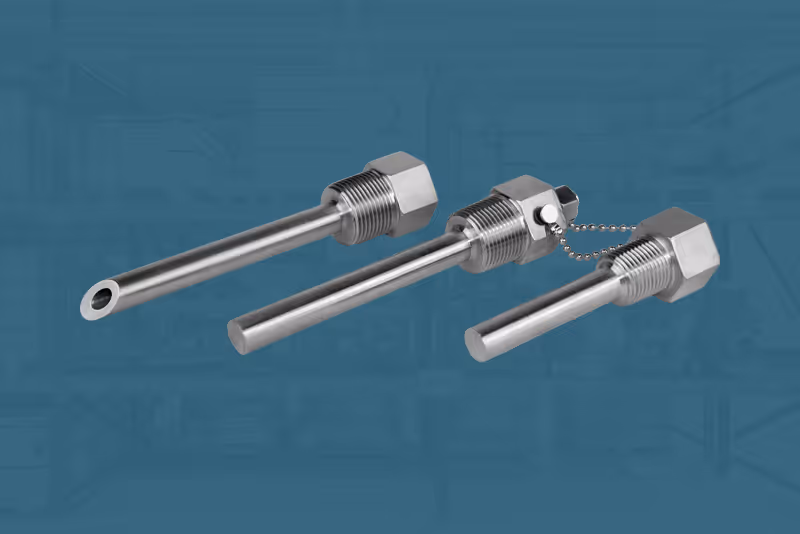
What’s the difference between thermowells and sample probes?
While thermowells protect temperature sensors, sample probes extract a representative sample of natural gas directly from the flow stream for gas quality, energy content, or contaminant analysis. Sample probes are designed to:
- Draw accurate, representative gas samples from the pipeline’s flowing gas stream
- Maintain sampling integrity by placing the probe tip in the correct part of the velocity profile
- Prevent bias from boundary layers, particulate matter, or phase separation
- Provide traceability and regulatory compliance for custody transfer and gas quality reporting
- Support gas chromatograph (GC) systems and other analyzers
The Axis sample probe design includes:
- 45° or square‑cut probe tips
- Angle markings on the hex head to verify correct flow orientation
- Various materials and insertion lengths to suit different line sizes and conditions
A thermowell is designed to protect your temperature sensor, preserve your pressure boundary, and keep measurement maintainable in harsh process service. The right thermowell for the job comes down to connection type, material compatibility, insertion length, and bore fit.
If you’re specifying thermowells for a new build or trying to stop repeated temperature probe failures, contact the Axis Measurement team. We can help you translate your service conditions into a thermowell configuration that holds up in the field without slowing down your schedule.
Axis is proud to support CCAMS by teaching a measurement class on February 17th on the following topic:
11:00 am – 11:50 am Manifold and Stabilizers: Installation & Best Practices hands-on session
Location: Matagorda Room
Visit us at Booth 25!
If you understand how a needle valve works, you’re in a better spot to choose the right material, pressure rating, and connection style for your job. That means better process control and more stable readings so you can trust the numbers you’re seeing in the field.
What is a needle valve?
A needle valve is a small, precision shut-off valve designed for low-flow, high-accuracy applications. Instead of a ball or gate that opens quickly, it uses a slender stem (the “needle”) that moves into and out of a small orifice.
In oil and gas, you’ll most often see needle valves in:
- Instrument air and gas lines
- Gauge root valves on manifolds and skids
- Analyzer sample lines and cylinders
- Custody transfer and fiscal metering systems
Where a ball valve is built for quick on/off service, a needle valve is built for fine throttling. It changes the flow a little at a time, in a consistent way that you can trust every time.
Needle valve components
Before you can really understand how a needle valve works, it helps to know what you’re looking at. The parts are simple, but each one has a specific job, and small differences in design can matter a lot out in the field.
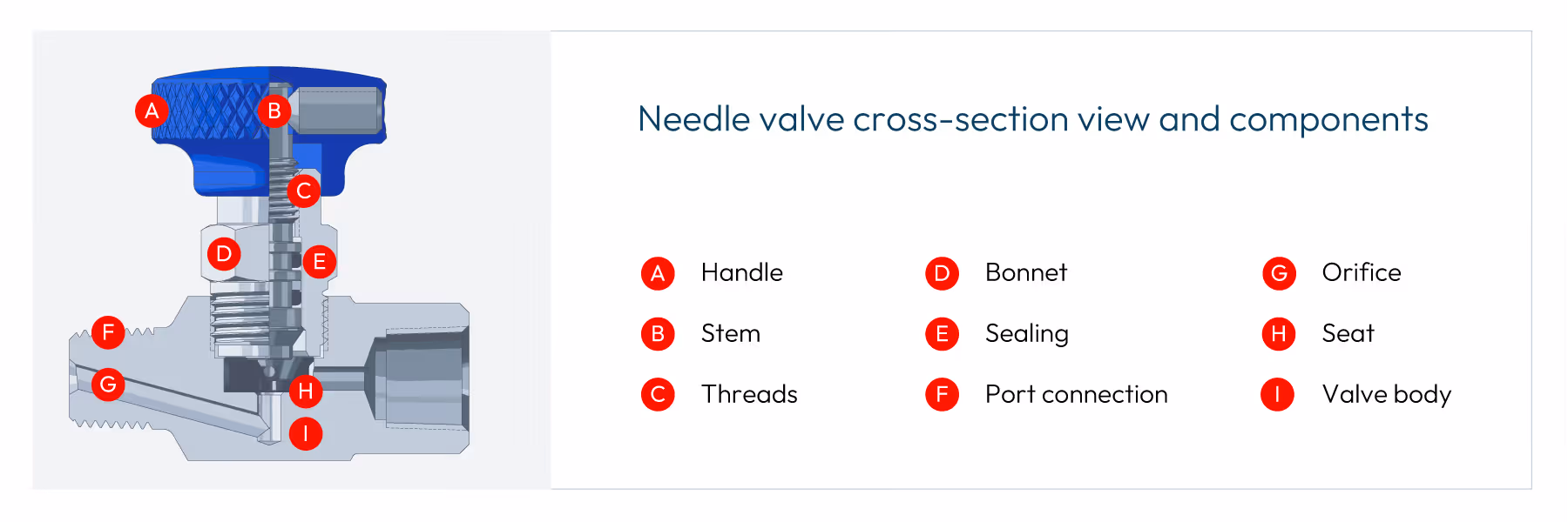
Valve body and ports
The valve body—usually stainless steel, carbon steel, or brass—contains the inlet and outlet ports and the internal flow path. On measurement skids and tube panels, you’ll most often see in-line bodies. Basic measurements are as follows:
- Common connection sizes: 1/8" to 2" (≈3.175–50.8 mm)
- Common thread standards: NPT, BSP, or metric
- Body styles: in-line or angle pattern for tight layouts
Bonnet and stem assembly
The bonnet is the piece assembled into the body containing the moving parts that control flow. Inside the bonnet you’ll find:
- Stem: Fine-pitch threads that turn handle rotation into precise up-and-down travel of the needle
- Packing: Sealing components around the stem (PTFE, FKM, FEPM, graphite, etc.) that keep the media from leaking to atmosphere
- Packing nut: Tightens the packing over time if slight stem leakage develops
Many modern instrumentation needle valves use a non‑rotating stem design. The stem travels through the packing independent of the needle, allowing non-rotational engagement with the seat. That small detail minimizes seat and needle wear, which helps the valve seal longer in high‑cycle or frequently adjusted service.
Orifice and seat
The orifice is the small opening that the media passes through. That’s what gives a needle valve its high pressure drop and precise control at low flow.
The seat is the fixed surface that the needle closes against, surrounding the orifice. Metal seats (like stainless or alloy steel) are common in liquid, high-temperature, or high-pressure service. Soft seats (like PTFE or POM) are often used in gas service when you need a bubble-tight seal and can stay within the seat’s temperature and pressure limits.
| CASE STUDY: Seat & seal selection in steam measurement manifold
Handle or handwheel
The handle is how you operate the valve. It translates your input into stem movement. Common handle types are round and T-shaped.
Because of the fine threads on the stem, the user has more control operating from fully closed to fully open. That’s on purpose. The needle valve spreads a small change in orifice size over multiple turns, which makes each adjustment smoother and less jumpy. In practice, that means you can edge closer to the flow you want instead of chasing it back and forth.
How a needle valve works
Once you know the main parts, the way a needle valve works is pretty straightforward. You’re simply moving a needle in and out of a small opening to change how much media can get through. The fine threads and small orifice are what turn that basic idea into a very precise control tool.
Here’s how needle valve positioning works:
- Closed Position: In the fully closed position, the needle tip is fully seated in the orifice. The tapered surface of the needle is pressed into the seat, creating a leak-tight seal. For a properly sized and installed valve with clean media, push it a little past finger‑tight. Over-tightening can damage the seat, especially in brass valves.
- Opening the Valve: Turning the handle counterclockwise lifts the stem through the bonnet threads. The needle retracts straight up away from the seat, opening a narrow gap between the needle tip and seat. Media starts to flow through that small opening.
- Flow Rate Control: As you continue to open the valve, the needle gap increases, allowing less resistance for media flow. The needle can be stopped at any position between fully open and fully closed to fine-tune flow rate.
- Fully Open Position: With the stem fully opened to the backseat position, the needle is entirely clear of the seat. Flow is limited mainly by the orifice and port size.
Needle valve pros and cons
Like any tool in the system, needle valves are great at some things and a less-great fit for others. Knowing where they shine helps you decide when a needle valve is the right call and when you should reach for a different valve style.
Pros
- High-precision flow control, especially at low flow rates
- Leak‑tight shutoff with relatively modest hand torque
- Compact and easy to integrate on panels, manifolds, and skids
- Can be built for high-pressure and extreme temperature applications with the right materials and packing
Cons
- High pressure drop due to the small orifice
- Not suitable for large flows or as the primary process isolation in large pipelines
- Needle and seat at risk of damage by solids and dirty media
- Handle position doesn’t clearly show open/closed like a ball valve handle
How to pick a needle valve
When you’re choosing a needle valve, it helps to walk through a simple checklist. The goal is to make sure the valve matches the media, the conditions, and the application in the field.
- Start with the media that’s flowing through the valve, whether gas or liquid. Identify corrosive properties and whether the media requires any special accommodations.
- Choose the body and bonnet material. 316 stainless steel is the go‑to for most oil and gas, chemical, and high‑pressure work. Brass is fine for moderate conditions with less corrosive fluids, while carbon steel or alloys are reserved for low-cost and non-restrictive environments.
- Confirm pressure and temperature ratings in your environment so you can choose internal valve components that meet those criteria.
- Determine the connections and orifice. Match the thread type and size to your existing tubing or piping. Look at the orifice diameter, not just thread size—it controls flow capacity and pressure drop.
- Pick a seat and stem design. Use a metal seat for high-temperature and high‑pressure services, or a soft seat when you’re working with gas and need a bubble‑tight seal. Pick a non-rotating stem design if the valve will see frequent cycling or adjustments.
| RELATED ARTICLE: Orifice meter installation effects and the need for flow conditioning
Get a needle valve that’s made to measure
Needle valves may be small, but they play a big role in measurement accuracy and flow stability. When you get the material, pressure rating, and seat design right, needle valves deliver reliable control without constant tweaking.
If you’re designing or upgrading a system and you want confidence in your valve choices, Axis Measurement is here to help. We carry a range of needle valves and can work with your team to match instrumentation components to real‑world pressures and temperatures, keeping your system accurate and production on schedule. Contact us to learn more.
Axis is proud to support ASGMT by teaching two measurement classes on September 18 on the following topics:
10:15 am – 12:00 pm Manifold and Direct Mount Systems and Valve Repair hands-on session
11:15 am – 12:00 pm Orifice Meter Installation and the Need for Flow Conditioning lecture class
Visit us at Booth 69!
Axis is proud to support the International School of Hydrocarbon Measurement (ISHM) by teaching one measurement class:
Manifold and Stabilizer Installation
This is a hands-on class demonstrating the installation and repair of manifolds and stabilizers out in the field. Learn how to install a range of measurement devices quickly, efficiently, and correctly for improved performance and to ensure the accuracy of your measurements.
Featured Presenter: James Dean
As Engineer, James Dean is responsible for improving and optimizing internal manufacturing processes, supporting the sales team by understanding products’ technical aspects, and heading up product development to meet customer demands.
James has over 11 years of experience working for leading manufacturers of instrumentation valves, manifolds, and piping products. He’s spent time in engineering sales support, engineering management, and general management roles. He also has a BSME with a minor in mathematics from Texas A&M.
Axis Attendees
We’re still the same company.
We remain the family-owned business that’s built on quality and dedication to our customers. For over four decades since we opened our doors as RJ Machine, we have made the best-quality products in the business. While we continue to manufacture the products you need at the high caliber you expect, we aren’t just a machine shop. You also trust us to handle more of your measurement needs, and our new name better reflects that.
Our team isn’t changing, either—the owners and employees are the same. You’ll still be working with the same people you always have.
We’re keeping the antler logo.
We first introduced the name Axis as a brand name for our newer products to help them stand out in a crowded market. Axis was named for the axis deer (also called a chital or spotted deer), since many of our customers know their way around a rifle and a deer blind. We chose a name that would resonate with them, and we used a set of crossed antlers as the brand’s logo.
Many of our customers over the years have told us how much they love the logo. So even as we re-evaluated our brand to ensure it would reflect the needs of our changing company, we knew this element wouldn’t change. Much like our commitment to our customers, the antlers aren’t going anywhere.
Our customers still come first.
We’re more than just a supplier or a machine shop. Over the years, we have built a hard-earned reputation for partnering with customers to solve their problems and support their every need. Whether you need a rapid fix or just have a question about a product, our team is quick to respond and get the solution you need. And like always, our after-sales service remains second to none, no matter where you’re located.
We still offer quality products you can depend on.
We continue to design and manufacture the precision-quality oilfield products you need, from manifolds to orifice plates and everything in between, giving you accurate measurement and minimal margin of error. Products are manufactured in Mexico for high volume and maximum value without cutting corners, so we deliver faster than our competitors with better value. We also maintain high inventory levels so you can get the products you need, when you need them, delivered right to your location.
We’re introducing new products, too.
Axis Measurement is a company of innovation. We are constantly expanding and bringing new ideas to the market to improve your measurement. Most recently, we have launched a large-bore, rapid-mount manifold that’s already redefining measurement in the field thanks to its reduced installation time. We hear our customers and the problems they face out in the field, and we are meeting those challenges with innovative improvements.
More patent-pending products are coming soon in competitive product spaces, so stay tuned for more updates.
---
The name Axis has resonated strongly with our customers. Axis is no longer just a brand we make. It’s who we are as a company. And as we move forward into the next 40 years, we’re excited to take that journey together with you.
Want to learn more about Axis Measurement products? Contact us and get the information you need.
Abstract
This paper discusses the effects of poor installations on orifice measurement and the best practices to achieve highest accuracy and performance. Flow disturbances are everywhere in pipelines and industrial applications. Knowing the types of disturbances, their effect on orifice measurement and how to correct those errors is valuable for anyone interested in accurate orifice flow measurement.
What is “Good” Flow
Most flowmeters are affected by the flow that they are trying to measure, orifice plate flowmeters included. Orifice plates measure best in “good” flow conditions and lose accuracy in “bad” conditions. There are several methods to describe and characterize good vs. bad flow conditions. When asked to describe good flow conditions, many users will use the term Laminar. This is a common yet minor misconception in flow engineering.
Laminar vs. Turbulent Flow
Laminar is a flow regime where the flow follows relatively straight lines down a pipe, Figure 1. If you were to follow a particle in the flow, it would go in a straight path and not cross paths with other particles flowing next to it. This is a regime with no turbulence. Laminar flow will happen in low flow and/or high viscous applications. In other words, the momentum forces are low and/or the viscous forces are high. Inherently this makes sense as higher velocities will encourage turbulence and higher viscosities will do the opposite.

As useful tool is the Reynolds number, which is a dimensionless number used to quantify whether a flow application is in laminar flow. The Reynolds number equations is a follows:
Re=VρD/μ
Re = Reynolds number, dimensionless
V = flow velocity, ft/s
ρ = density, lbm/ft3
μ = dynamic viscosity, lbm/s·ft
The numerator of this equation combines the momentum forces in the flow, velocity, density and size. While the denominator are the inertial forces, viscosity. This follows the logic described earlier. The lower the Reynolds number, the more likely the flow regime is in a laminar state. Laminar flow is more likely to exist where the velocity, density or size is small, and/or where the viscosity is high. The commonly accepted value of laminar flow is Re < 4000. As the Reynolds number increases, the flow regime enters a transition phase between 4000 and 10,000. Above 10,000, the flow regime is considered to be turbulent.
Reynolds number - Flow regime
0 – 4,000 - Laminar
4000 – 10,000 - Transition
>10,000 - Turbulent
Turbulent flow, Figure 2, is the opposite of laminar flow in that the flow streams do not follow a straight or regular pattern. In turbulent flow the flow streams cross, small eddies occur, and mixing is more common. The word “turbulent” rightfully has negative connotations. No one wants to be on an airplane and fly through turbulence.

So why is Laminar the incorrect term to describe good flow? It’s not. It’s just not the world in which our flowmeters live. The vast majority of industrial pipelines are in the turbulent flow regime. Virtually all gas flows are turbulent due to the high velocities and low viscosities. Even most liquid flows are turbulent, except for some high viscosity products such as crude oil. Turbulent flow is better for orifice measurement because orifice plates were designed to measure it and their performance is well understood in those conditions.
A side note: Reynolds number is a very helpful in flow measurement. Since it is a dimensionless number, Reynolds can use a single number to describe a flow application. And that number can be used across applications. If the Reynolds number for an application is below 4000, that application is in the laminar flow regime, regardless of the size for example. Reynolds number is used when calibrating a flowmeter. Since the Reynolds number describes the flow in a single number, users can calibrate on one fluid and use the flowmeter in another fluid, knowing the performance will match at equal Reynolds numbers.
Flow profile
A better way to describe understand good vs. bad flow is the presence or absence of flow disturbances. Long, straight, unobstructed pipe will create undisturbed flow. The addition of common pipe elements will create disturbances. Common pipe elements can include single elbows, tees, two elbows in series, partially closed valves, pipe reductions or expansions, thermowells, and many more.
Just like the Reynolds number is a tool to understand the flow regime, the flow profile is a tool to visualize whether flow is disturbed or not. The flow profile attempts to show the velocity at difference points across the diameter of a flowing pipe. This can be physically measured in several ways such as with a single point Pitot tube sensor or with more complex tools such as laser doppler velocimetry. Typically, the view is across a full diameter, crossing through the midpoint of the pipe. A typical flow profile looks like Figure 3 for turbulent flow. Each arrow represents the velocity at points across a diameter of the pipe. The velocities are higher in the center of the pipe and lower near the pipe walls.

The friction on the pipe walls causes drag which slows down the fluid flow nearest to it. As the flow continues down the pipe, the next layer away from the pipe wall is slowed down slightly less. And so on until the effect of the pipe wall friction no longer affects the velocity. This is called the boundary layer effect and is created whenever flow passes over a surface. Notice the shape of the Figure 3 profile in turbulent flow is different than the shape in Figure 1. Laminar flow has a characteristic “bullet” shaped profile and turbulent has a flatter shape.
Well-developed flow is created when the boundary layer is fully established without disturbances. Put another way, well developed flow will not change its profile as it moves down the pipe. In the industrial flow measurement world, it’s also the definition of good flow and is very important in understanding flow through an orifice.
Power law estimation
When comparing whether a flow profile is well developed or not, a useful tool is the power law estimation. The power law gives a numerical estimation of a well-developed profile. The power law equation is:
u/umax = (1-r/R)1/n
u = velocity at measurement point
umax = max velocity in pipe
r = radius at measurement point
R = pipe radius
n = power
A value of n = 7 is typically used to fit the velocity profile for fully developed, turbulent flows. A higher value of n creates a flatter profile. A lower value creates a more bullet shape profile associated with laminar flow. A power law curve where n = 7 is shown in Figure 4.

As flow is disturbed with the addition of pipe elements, the flow profile will change. For example, flow through a single elbow creates a skewed profile. The high velocity “core” of the pipe will be pushed to the opposite wall of the pipe, creating an asymmetry where the maximum velocity is no longer in the middle of the pipe. Single elbows and other elements can create asymmetry in the flow profile which is shown well in Figure 5.

Swirling flow
The flow profile does not capture another type of flow disturbance called swirling flow. Swirling flow is when the flow has a crossflow element. Without swirl the flow will run straight down the pipe, with 0° in relation to the centerline of the pipe. If crossflow is present, the flow streams can have a swirl angle, up to 20° in severe cases.
There are two general types of swirl disturbances, Type 1 and Type 2 swirls. Type 1 swirl moves in one directional rotation across the pipe. This is also known as whole body swirl, Figure 6. Close coupled double elbows out of plane are a common cause of Type 1 swirl, along with headers, pumps and compressors. Type 2 swirl introduces two counter rotating swirls rotating in opposite directions, Figure 7. This is usually created after single elbows.


Orifice plate flow measurements
Orifice plates measurement have a century-long track record of continuous use and improvement in industrial applications. No other flow technology has the international volume of understanding and acceptance as orifice plates. Orifice plates are often described as “a hole in a plate” and often ridiculed for that simplicity. Yet it is the simplicity of an orifice plate that makes it so elegant. Leonardo da Vinci once said, “Simplicity is the ultimate sophistication”. The design of the orifice plate makes it possible to manufacture with precision and repeatability. Making one orifice plate measure the same as the next one with matching dimensions. A dimensional inspection is all that is needed to “calibrate” an orifice plate.
Knowing that two identical orifice plates will measure the same (within known uncertainties) is one of the reasons why they are the most widely used industrial flow technology even after 100 years. In today’s world, a user can replace an orifice plate and know the uncertainty of the measurement will not change, even without a flow calibration – something no other flow technology can match!
This also means that a flow calibration once done on a known orifice plate size, can be applied to all other matching orifice plates. Over the decades a massive database of traceable orifice calibrations was completed and used to create the de facto standards for orifice flow measurement. The American standards are the AGA Report No 3 and API 14.3 standards for natural measurement using an orifice plate. The international standard for orifice plates is ISO 5167.
The orifice performance in that technical database (which includes over 30,000 data points!) was tested in well-developed flow conditions. The standards confirm that measurement in matching conditions and dimensions will perform at custody transfer levels of accuracy. And since all the data points were tested in well-developed flow conditions, the standards require the same for accurate measurement.
Effect of flow disturbances on orifice measurement
If a user’s flow conditions are not well developed, with asymmetric or swirling flow, the accuracy will be affected. The effect on accuracy will depend on several factors, including the type of disturbance and the relative distance of the disturbance to the orifice location.
As the distance from the disturbance to the orifice plate increases, the flow will naturally return to a well-developed state due to the turbulence in the flow (turbulence helps us here). The distance needed to return to well-developed flow depends mostly on the type of disturbance. The AGA/API standards recommend up to 44 pipe diameters of straight pipe after double elbow to achieve well developed flow.
Shown below are two sets of flow calibration data from Mattingly and Yeh measuring three different orifice bore sizes (beta ratios) at various distances from a disturbance. Figure 8 shows single elbow effects.Figure 9 shows effects from close coupled, double elbows out of plane.


The effect of the disturbance diminishes with distance, approaching zero effect. Notice the effects on accuracy of the orifice plate measurement can be up to 5% after a single elbow using a high beta ratio. The effect lessens using smaller beta ratios. Also notice the x-axis scale of the double elbows chart is much larger than the single elbow chart. This confirms that Type 1 swirl has a much longer lasting impact on flow measurement than Type 2 swirl.
Improving flow conditions
A user can make a determination about their installation knowing the above information. They have three options available to them:
- The user could plan the measurement point as far as possible from the disturbance. The more distance means the more likely the flow is well developed at that point. Some users may have plenty of straight pipe in their system and can meet the minimum requirements in the standards. For most users, creating the necessary straight inlet piping will come with additional expense.
- The user can accept the additional uncertainty that comes with a bad installation. This might be a fine solution in applications with low accuracy requirements. But most industrial applications cannot accept accuracy shifts on the order of ±5%.
- The user could follow the most common practice in the industry: use a flow conditioner.
Flow conditioners
The user of flow conditioners is an industry best practice for ensuring optimal flow measurement with an orifice plate. Flow conditioners come in a variety of designs but have one common goal: to condition the flow to well-developed conditions ahead of an orifice flow measurement point regardless of the disturbance ahead of it.
In the AGA Report No. 3, Section 2.3.1.7 “Flow Conditioners” classifies flow conditioners into two categories: straighteners and isolating flow conditioners.
“Flow straighteners are devices that effectively remove or reduce the swirl component of a flowing stream but may have limited ability to produce the flow conditions necessary to accurately replicate the orifice plate coefficient of discharge database values. Isolating flow conditioners are devices that effectively remove the swirl component from the flowing stream while redistributing the stream to produce the flow conditions that accurately replicate the orifice plate coefficient of discharge database values.”
Flow straighteners
Flow straighteners are low blockage, swirling reducing flow conditioners. Common examples of flow straighteners are tube bundles, example shown in Figure 10 and fin-type straightening vanes, example shown in Figure 11. Tube bundles can be designed with 19 or 7 tubes concentrically grouped in the pipe. The terminology around these can be confusing as tube bundles are sometimes sold as straightening vanes, but both fall into the category of flow straightener as described in AGA 3.
These types of flow conditioners are designed to remove swirl with their elongated dimensions. But since they are low blockages, they do very little to correct he asymmetry in the flow profile. In fact, Mattingly and Yeh also showed that flow straighteners can actually make asymmetry a more persistent flow disturbance, lasting much longer in terms of distance. This is because the flow straighteners will capture the asymmetry entering each tube and reduce the type 2 swirl. By reducing the type 2 swirl, the natural turbulence is diminished and the asymmetry does not break down as quickly.
In short, flow straighteners are not recommended for orifice plate measurement.


Isolating flow conditioners
Isolating flow conditioners have a blockage factor that forces the flow profile to redistribute as it passes through. This redistribution controls both the asymmetry and swirl disturbances. The design is typically a perforated plate with multiple holes designed to create a well-developed flow profile as soon as possible after the plate.
The search for the ideal pattern of holes to do this job was the subject of much research in the 1990’s as the need for flow conditioning became more and more relevant. A summary of the research from researchers such as Laws, Karnik, Zanker, Gallagher and others is fascinating but outside the scope of this paper. The most widely accepted design of this research was developed by Laws and has become known as the NOVA 50E design.
The NOVA 50E design, Figure 12, is a multi-hole flow conditioner with concentric rings of openings. 16 smaller holes around 8 midsized holes around one large central opening. The size and position of each hole is meant to stimulate the formation of a well-developed flow profile regardless of upstream disturbances. The “50” designation indicates that the plate has approximately a 50% blockage area in the flow path. The success of this design is the balance of three factors: 1) enough blockage to redistribute the flow profile, 2) large enough holes to allow passage of particles and 3) enough opening to reduce the pressure loss across the plate as much as possible. The NOVA design meets the requirements of AGA 3 Section 2.5.5 and APPENDIX 2-D.

The design is universal for all flow conditions and disturbances. This advantage means a user can have one design flow conditioner for various pipeline installations and conditions. And it gives the user the assurance that most flow disturbances will be removed prior to flow measurement. For as much testing and research has been done of the effects of flow disturbances in a pipe, a user does not know the flow regime and development of their flow profile. Having a flow conditioner improves orifice plate measurement in all standard applications.
Conclusion
The use of a flow conditioner is recommended for all high accuracy orifice plate measurements. The recommended type of flow conditioner is the NOVA 50E design to remove most flow disturbances such as asymmetry and swirl. And users will benefit from the assurance that a well-designed flow conditioner will remove any unknown flow disturbances and problems that could diminish their measurement accuracy.
[1] Effects of pipe elbows and tube bundles onselected types of flowmeters, G.E. Mattingly, T.T. Yeh, Flow Measurement Instrumentation, Vol 2, January 1991
[2] US Patent 5,341,848 “Flow Conditioner”, 1994
We want to hear from you.
